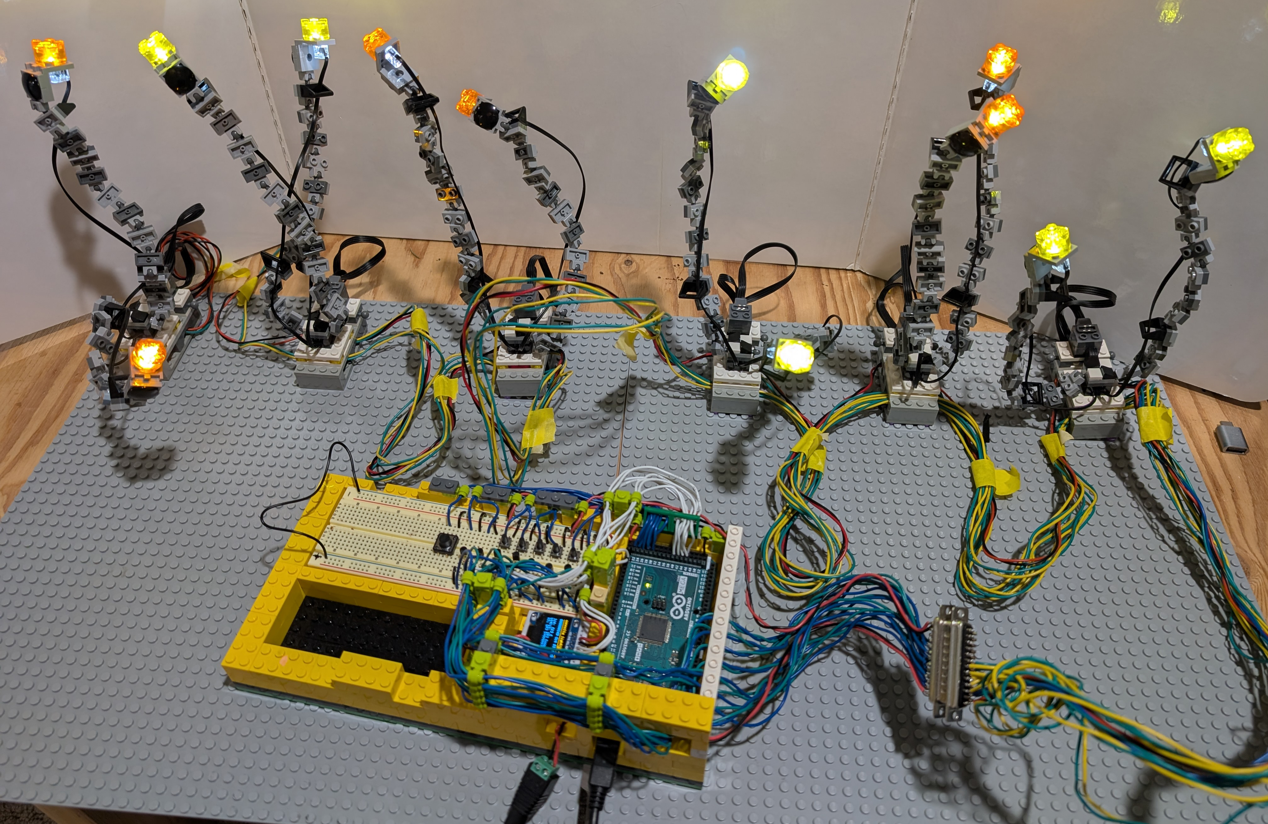
The cool light stand array integrates a set of Lego Power Functions Lights with an Arduino controller.
This was designed to be part of a Lego exhibition; it was placed around a larger exhibit to add highlighting and a little fun. Its functionality includes:
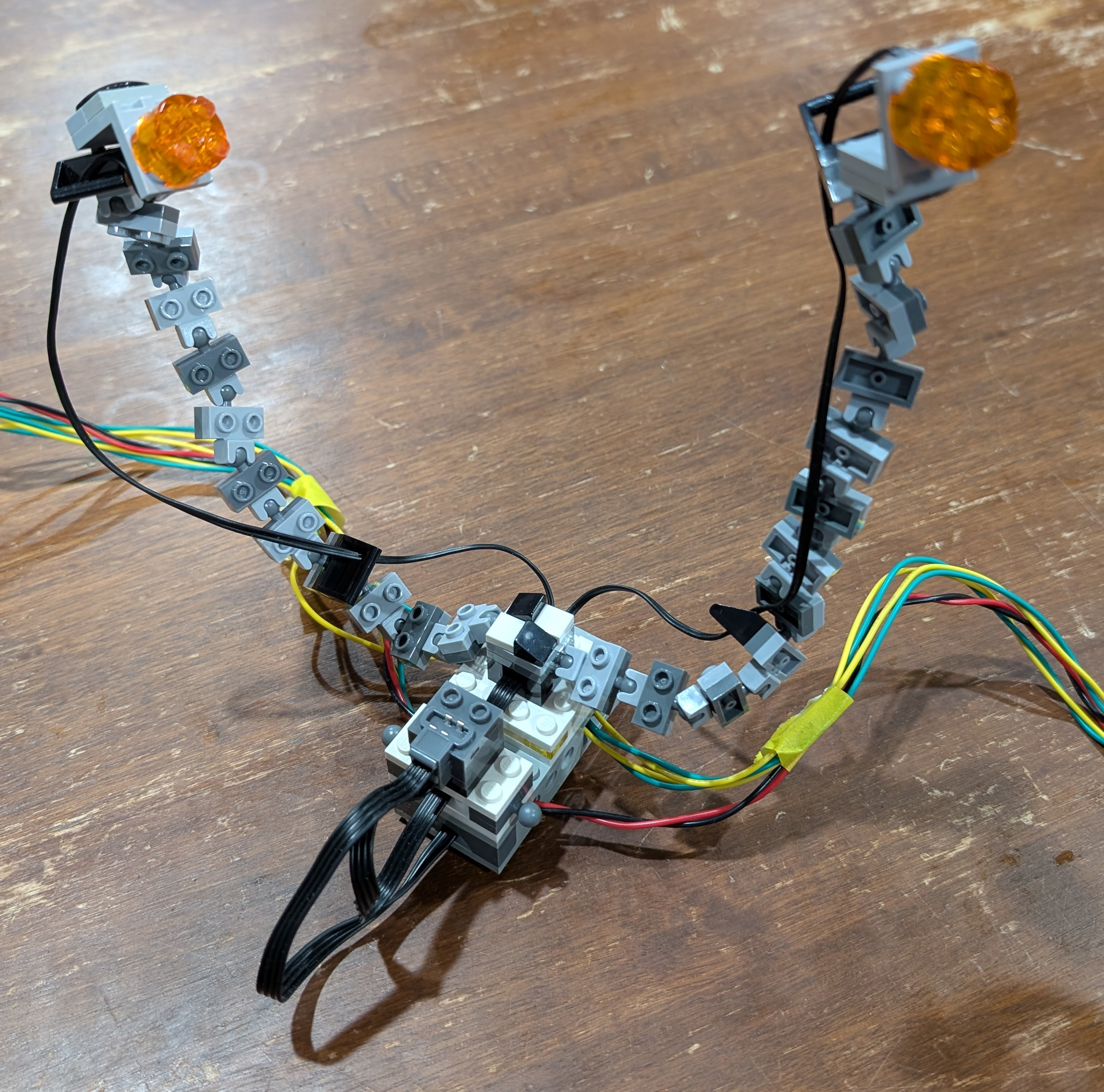
- Six individual light stands, each with two LEDs mounted on adjustable arms that allow them to be pointed in any direction.
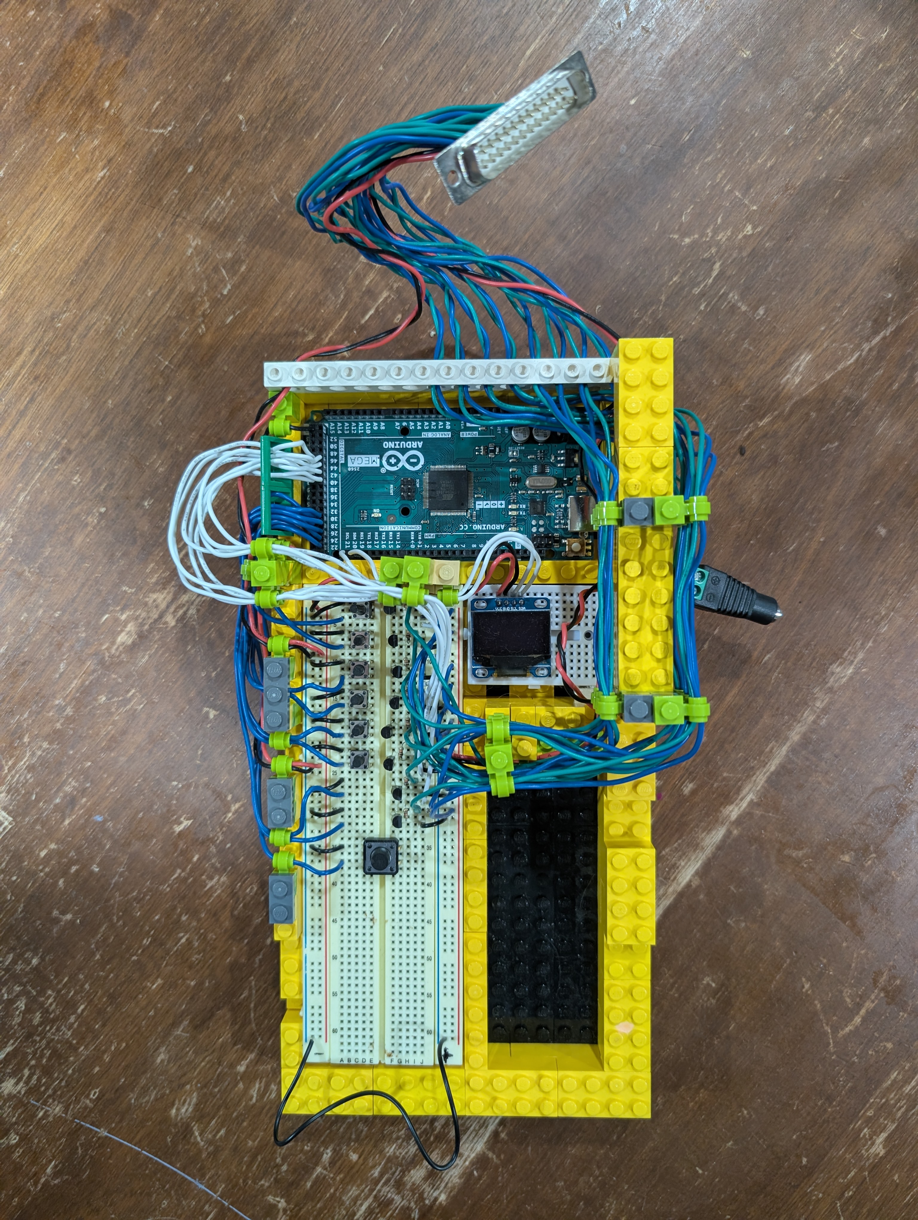
- A control unit, where all six light stands can be individually turned on/off via push-buttons.
- A blink-mode button that can rotate between 6 different blink-modes, coordinated across the entire set of lights.
- Constant All-On
- Blink Fast
- Blink Slow
- UniDirectional Flow
- UniDirectional Flow Slow
- BiDirectional Back and Forth
Note: the controller was internally wired to control up to 8 lights, so it includes 8 transistors and uses 8 output pins out to the DB25 connector and beyond. However, only 6 lights were actually wired up to the array before the project was completed (so two of the transistor sub-circuits are currently unused).
Lego Power Functions Pinout
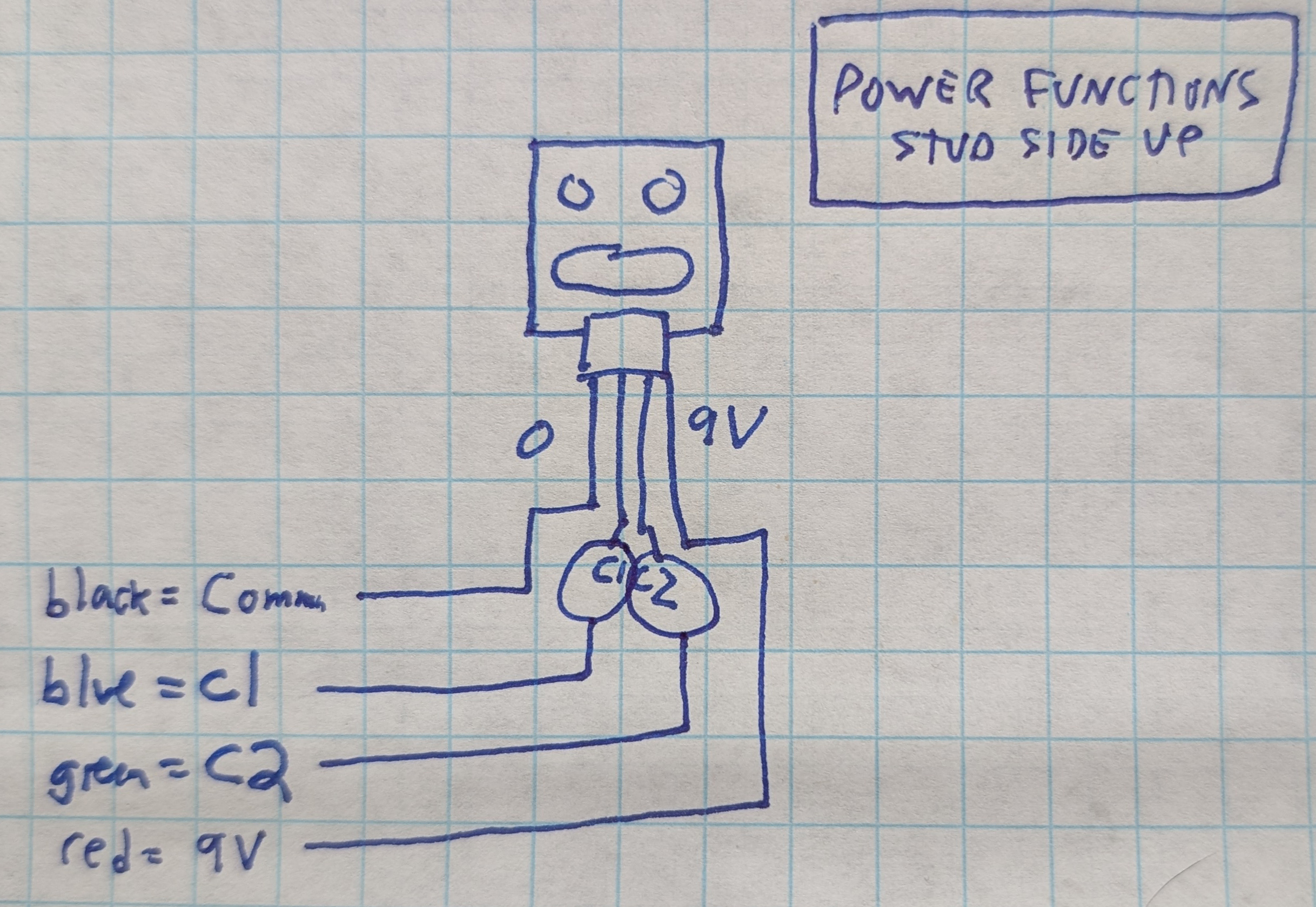 |
- 4 wires into a standard Lego interface used in all Power Functions modules
- 1 wire is common ground, 1 wire is a constant 9v, and the other 2 wires are used to control the lights; raising the voltage in either line will turn the lights on.
- This implementation always uses the C1 line and ignores C2.
|
Controller DB25 Pinout
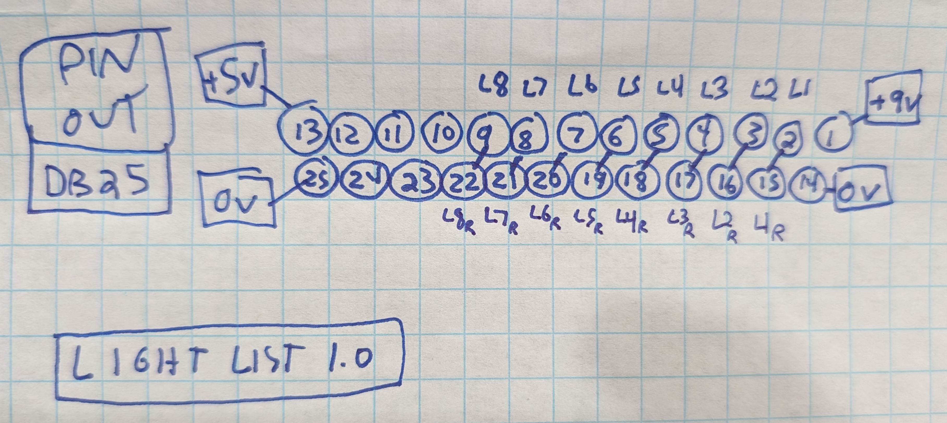 |
- 25 wires into the standard DB25 interface (used in old printers and other equipment from the 80s/90s)
- Outermost pins (13, 1) carry constant 5v and 9v power, with pins 25 and 14 connected to ground.
- Each light uses two pins, starting from pin 2, and pairing with the pin beneath it. (This was wired for 8 lights, even though the final version only has 6 lights attached to it).
- There are 5 unused pins, allowing up to 2 more possible lights with this design (for a total of 10).
|
Arduino - Transistor - Light Circuit Pinout
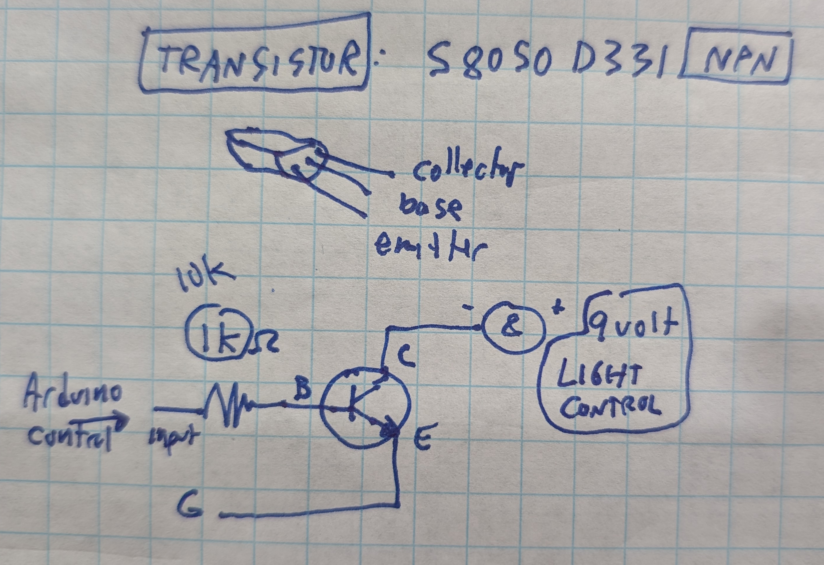 |
- Transitors are used to control the 9v lines (required to power these types of lights) from the 5v Arduino digital i/o pins.
- For each light, the Arduino output pin for that light is connected to the base of the transistor, via a 10K Ohm resistor.
- The transistor emitter line is connected to ground. The collector line is connected to the ground line of the light.
- The other pole of the light is connected to a constant 9v line. When the Arduino raises the voltage level on the base line, this opens up the transitor switch, completing the light circuit through the ground line, and allowing the 9v circuit to flow (and power the light).
|
OLED Screen Pinout
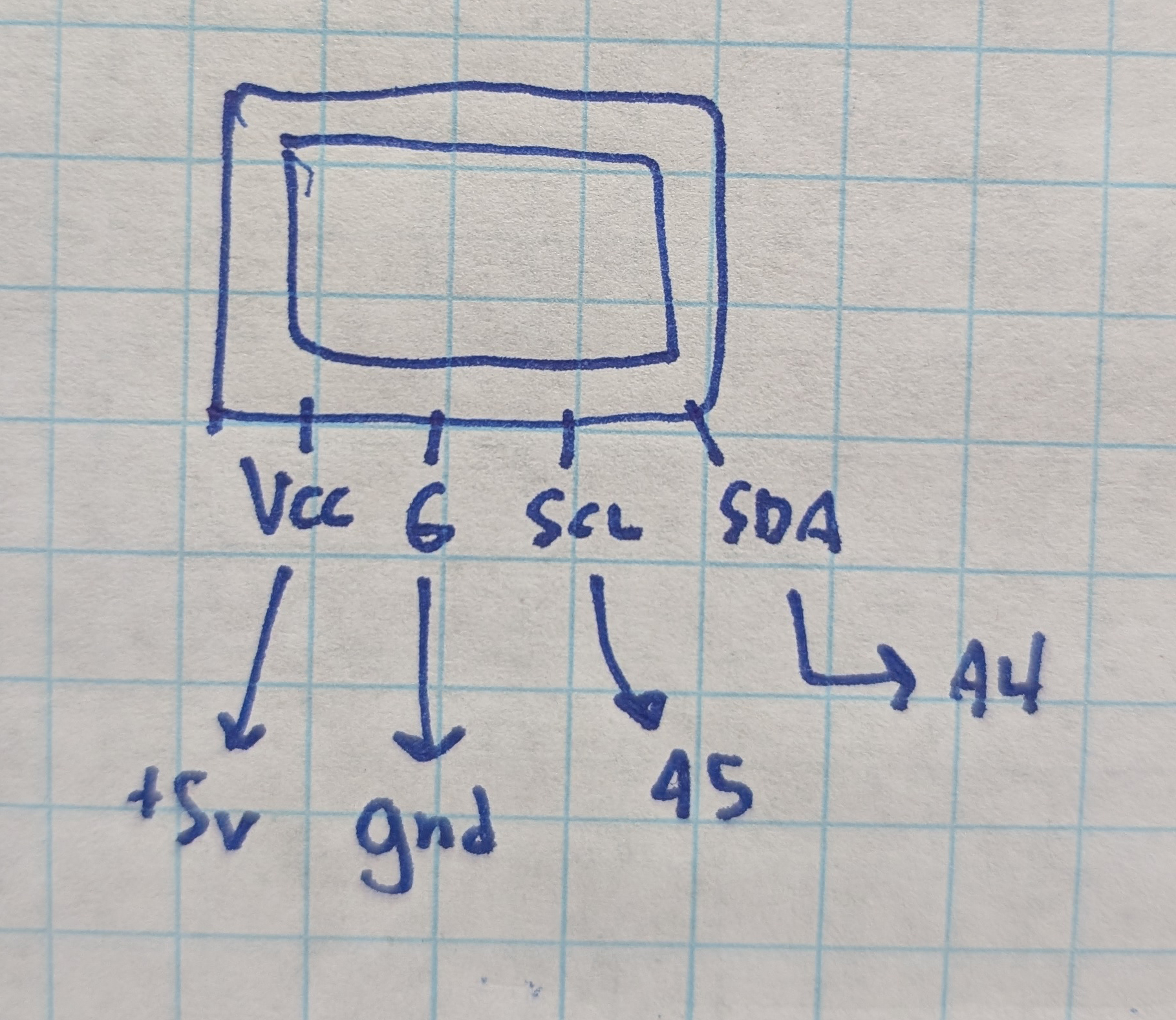 |
- 4 pin interface
- 5v line and ground line are hooked right up to those same pins in the Arduino
- SCL and SDA lines are connected to the corresponding SCL and SDA pins on the Arduio; for example, on the Mega the SCL pin is digital pin 21, but on the Uno its implemented on analog pin 5.
|